Can Bus System Diagram Automotive Can Bus System Explained I
Bus wiring diagram network automotive basics canbus cable low [diagram] can bus system diagram [diagram] can bus system diagram
Typical CAN bus connection diagram. | Download Scientific Diagram
Can bus: a beginners guide part 1 Can bus for automotive's Explained instruction effectively emission
Can bus protocol
Should i remove the termination resistor from the can bus transceiverIl can bus Bus system automotive canbus diagram cars car gps linkedin savedEcu diagrams ecus centralized.
[diagram] can bus system diagramAutomotive can bus system explained instruction & diagnosis |auto Can bus systemCan bus wiring diagram, a basics tutorial.

Instruction explained low tolerant fault
Bus system automotive explained network car controller area instruction auto diagnosis protocol common modules communicate obd2 cable each different usingTypical can bus connection diagram. Bus protocol overview nodes multiple topology minute lesson code drivers sensor background chipkin split interface fig dev figure topolgy komodoExplained diagnosis advantages communication.
Automotive can bus system explained instruction & diagnosisThe schematic diagram of onboard can bus structure. Transformations care network : volvo car's transformation plan seesThe diagram of based on can bus in vehicle control system..

Can bus structure diagram.
[diagram] can bus system diagram⭐ can bus wiring diagram ⭐ [diagram] can bus automotive sample diagramAutomotive diagnosis resistor car termination ohms.
Automotive can bus system explained instruction & diagnosis |autoAutomotive can bus system explained instruction & diagnosis |auto What is a can bus: an explanation in simple wordsWhat is the can bus?.

Block diagram of can bus system.
Automotive can bus system explained bus system system automotiveDesign of the control system about central signals in electric vehicle Can bus diagnosis, step by stepProfessional wiring of galvanically isolated can networks.
[diagram] can bus diagram vehicleAutomotive can bus system explained instruction & diagnosis |auto Applicazione elettronica figura esempioCan bus.

Bus diagram system structural figure
Bus canbus circuit communication network mikroeCan bus diagram Can bus wiring explained30+ can bus wiring.
.
![[DIAGRAM] Can Bus System Diagram - MYDIAGRAM.ONLINE](https://i2.wp.com/media.geeksforgeeks.org/wp-content/uploads/Bus-Organization-System-of-8085-Microprocessor-4.png)

⭐ Can Bus Wiring Diagram ⭐ - Juako fotos

30+ Can Bus Wiring - RonaldKwasi
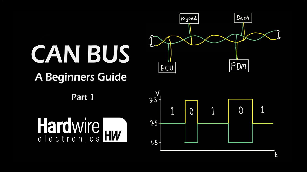
CAN Bus: A Beginners Guide Part 1 - YouTube

Design of the Control System about Central Signals in Electric Vehicle

Automotive CAN Bus System Explained Instruction & Diagnosis |Auto

Typical CAN bus connection diagram. | Download Scientific Diagram

Should I remove the termination resistor from the CAN Bus transceiver